
This digg button kit is manufactured by Adafruit technologies, and there are lots of details on their product page. Plus the instructions are available online including lots of photos at ladyada.net. You can order the kit online or if you want to make it yourself you can just look at the parts list at ladyada and buy all the bits yourself. Even the board design is available if you want to get that made. But buying the kit is a whole lot easier and the mail order service is good. List price is USD15, and unregistered shipping to Europe adds another 8 dollars or so.
The "Digg" part of the name (and branded on the board itself) is a gimmick based on the popular website digg.com. But this button doesn't have any online capability, it's just a battery-powered button-and-LED toy. Very simple but has the great advantage of being freely modifiable. Some ideas are given at the Ladyada site, including adding a USB power supply (note: not a USB data connection!) or more interestingly adding an interface so you can reprogram the microprocessor to do other stuff. You can think up your own mods after that, including bigger displays or fancier behaviour.
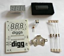
The digg button kit contents laid out
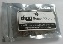
The digg button kit in its packet
The kit, as shown on the right, includes everything you need to build the thing, except tools. At least a soldering iron, solder, and cutting pliers are required. Everything else (the main board, the battery holder and battery (even a spare battery!), the microprocessor chip, the LED display, the switch, the resistors and capacitor) all come in the box. If you have additional tools like solder suckers, component holders, continuity testers etc then you can for sure use them but they're not really necessary for a basic kit like this.
As with the microbug kit, you need a suitable work area, with plenty of space and plenty of light. And a power supply for the soldering iron of course. Lay out some paper over the table to protect it, if you don't want scorch marks and solder splashes on it.
Next, check the online instructions (print them out if your work area isn't near the screen), open the packet and check that you've got everything you need. Lay all the components out and check you've got the right numbers of everything. It's a pretty simple circuit design so there shouldn't be any problems - there's only one type of resistor (all four are the same), only one capacitor, and the LED display can only fit one way in the holes. You do have to be careful to plug the microprocessor in the right way but as long as you match up the notch with the board then it should be no problem.
Simply follow the comprehensive instructions and solder the components one by one - the LED display, the button, the resistors and capacitor, the chip and the battery holder. The chip is the only bit requiring a bit of care with getting it the right way round.
Take care with the soldering not to use too much solder and not to connect pads which shouldn't be connected. Check each joint and if necessary clean up any which aren't quite right. Don't plug the battery in until you're sure!
Here are some more resources to help you figure out this project - as already mentioned it's a very straightforward kit but it's still fun to watch someone else build it and point out the possible gotchas:
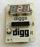
The completed digg button kit
ready for testing
It could be that the battery holder is quite tight, so be careful inserting the battery (the right way round!) and bend the holder tabs if necessary. The chip is already pre-programmed so when you put the battery in it should already run the program and show a "0" on the LED display. Pressing the button should show the "dug" message briefly and then increment the counter. Repeated presses keep on incrementing the counter, but if you press and hold the button, it should reset the counter to 0.
Another experiment - increment the counter to a known number, take out the battery, and then re-insert it. What do you expect, will it forget the value of the counter? Try it and see!
Another experiment - while the battery is in, short out the top two "X1" buttons on the left of the board (a snipped-off resistor leg bent round to touch the top two contacts is ideal). It should then display a scrolling message repeatedly - we'll come back to change this scrolling message later.
Another trick if you've got lots of patience - see what happens when the counter scrolls past 999 - if you look at the source code you may be able to guess what happens...
So now the counter is working, and it's time to dig(g) a bit deeper to see how it works and how we can modify it to do something slightly different. Take a look at the schematic online, try to figure out why it needs four resistors when there are only three digits on the display, try to see how many spare pins we've got on the chip which we're not using yet. Could we use them for extra inputs or outputs?
There are some good suggested mods on the ladyada page, we'll try and go through some of them here. High on the list of mods are replacing the coin cell with a USB connection (so we don't have to keep buying coin cells to power the kit), connecting it up to the computer to edit the memory contents of the microprocessor, and eventually modifying the source code and loading new instructions into the chip.
The next step is to build a parallel cable to hook the board up to a computer's parallel port for reprogramming.