
Following on from the introduction page in which we built the simple Digg button kit, the next step is to build an interface cable so that we can look at and modify the chip's memory contents and eventually reprogram the code. We're going to connect it to the computer's parallel port, and use free software to interact with the microprocessor.
There are a few different ways you can make the interface cable, from the dead simple (soldering the tabs on the board directly to the parallel plug) to the fancy (making it neater, removeable, reusable and so on). There are a couple of very good online descriptions giving some ideas:
For this experiment we'll make a semi-permanent cable - this will mean that the board itself doesn't have to have an ugly parallel port plug dangling off it (as in ladyada's basic solution) and also lets the board be a bit further away from the back of the computer during programming. It also avoids the dodgy connections of the instructables solution by giving a more solid plug/socket connection.
It's a simple parts list, based on the very good instructions at ladyada. Apart from the 25-pin parallel port plug (also known as a DB-25), and the cable itself, you just need the three resistors (roughly 1 kiloohm) and whatever you decide to use for the removeable connection. Ask for advice from your local friendly electronics store, I was recommended to use an audio DIN plug and socket as only five of the wires are needed. The cable is also five-core and fairly lightweight.
The total cost of the parts from pusterla in Zürich was around 9 CHF, which is about 6-7 EUR.
As for tools, we'll need the same soldering iron, solder, cutters and work area which we used for the digg button itself, plus we'll use a cheap multimeter to check the cable connections.
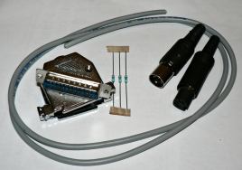
The parts for the parallel cable laid out
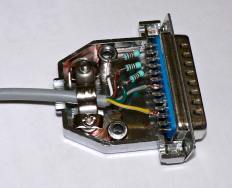
The assembly of the parallel port plug
including resistors
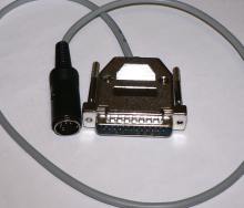
The first part of the cable assembled
As we're making it, the cable is in two parts, from the parallel port plug to the DIN plug and from the DIN socket to the board. We start by following the instructions at ladyada to identify the pins on the parallel port which we wish to use and tinning those with a small amount of solder. We also need to identify which pins require resistors and which not. The resistors are there to prevent the computer's parallel port from being "fried" (in ladyada's words) so I had expected them to protect the inputs to the computer. However by looking at the pinouts on wikipedia one can see that they're actually protecting the outputs of the parallel port. The only input is the 'busy' signal which is a simple wire connection. The other wire connection is the ground.
As the parallel port plug is quite a large construction, I decided to hide the resistors in there, making the cable neater. After cutting the resistors to length and soldering them directly to the pins, they can be bent to fit inside the casing without touching each other. A perfectionist would of course use heatshrink tubing or electrical tape to guarantee isolation once the soldering is complete.
The next step is to attach the cable to the plug. There are five coloured wires within our cable, and it doesn't matter which we use for which pin, as long as we keep careful track of which is which. Obviously the pins on the parallel port need to be connected to exactly the correct tab on the board, so triple-checking is advised. Keep careful notes as you go.
Once the plug is secured and the cable gripped securely, we can cut the cable to the desired length (leaving enough for the second part of the cable!) and attach the audio plug. Keep the smaller of the plug/socket pair on the board if possible, and put the larger part on the cable. Strip the wires to the required length, and slide the rubber plug moulding on to the cable. Then tin the wire ends and solder carefully (avoiding touching the neighbouring pins!) to the plug. Again, some heatshrink or insulating tape would be useful here to keep things separated. And again, note carefully which colours are attached to which pins on the plug. Then put the plug together and the first part of the cable is complete.
The second part of the cable is simpler, but it helps to keep the colours in the socket the same as those in the plug. Remembering that the plug and socket are mirror images of each other, attach the wires as before to the pins so that the colours match. After protecting the connections, assemble the socket so that all that remains is to solder the other end of this cable to the board. But before we do that, let's test the cable so that we're absolutely sure that the connections are right, and that there are no short-circuits or breaks anywhere along the length. Breaking the board would be bad but "frying" the parallel port on the computer would be very bad!
There are several things we can check on the cable before we plug it in. Firstly, are there any short-circuits, so that pins on the parallel port are connected to each other when they shouldn't be? Secondly, are the correct pins on the parallel port connected to the correct colours on the bare end? And thirdly, are the resistances across the connections correct (either direct connections or about 1 kiloohm)?
We can check all of these things with a simple multimeter - this is a useful gadget which can be set to measure voltage (in volts), current (in amps) or resistance (in ohms). I got a simple digital one from Migros in Zürich for 26 CHF (about 16 EUR). If we set this to measure resistance, we can check the pins of the parallel port against each other (which should give no connection or unmeasurably high resistance). We can also check the pins which should be directly connected against their corresponding coloured ends (which should give direct connection or very very low resistance). And finally we can check those pins protected by resistors against their corresponding coloured ends (which should give a resistance close to the nominal resistor value).
If everything double-checks ok, we can then go ahead and solder the free end of the cable to the digg button board.
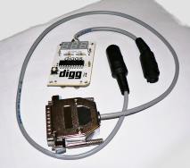
The assembled cable soldered to the board
After taking one more look at the ladyada guide, we can solder the final 5 connections to the tabs at the top of the board. Note that the wide tabs are not used, and one of the six thin tabs is also not used here. The final step is to make some neat fixing for the DIN socket on the board so it doesn't dangle around too much and doesn't stress the solder joints. I chose to mount the socket sideways on the back of the board, with a small loop of cable up to the tabs. A more robust solution would be required if this board was going to get any kind of abuse.
And that's the cable finished! The board is made more bulky by this extra socket on the back and the loop of cable is not quite ideal, but the connection is solid and the cable gives a reasonable flexibility while programming the board. So now we can connect the board to the computer, so the next step is to try it out using some free software.